
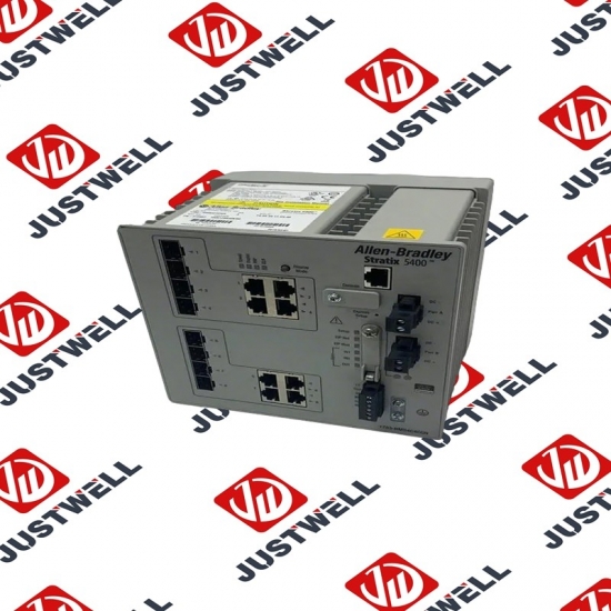
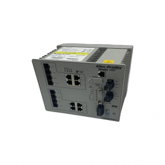


1738-RN002 A-B Power Board
Item NO.:
1738-RN002Payment:
T/TProduct Origin:
USAColor:
NewLead Time:
IN STOCK1738-RN002 A-B Power Board
Installation Requirements Related to EN 61800-3 and the EMC Directive • The drive must be earthed (grounded) as described in Connections and Grounding on page 45. See General Grounding Requirements on page 16 for additional grounding recommendations. • Output power wiring to the motor must employ cables with a braided shield providing 75% or greater coverage, or the cables must be housed in metal conduit, or equivalent shield must be provided. Continuous shielding must be provided from the drive enclosure to the motor enclosure. Both ends of the motor cable shield (or conduit) must terminate with a low-impedance connection to earth. Drive Frames A...E: At the drive end of the motor, either a. The cable shield must be clamped to a properly installed “EMC Plate” for the drive. Kit number 25-EMC1-Fx. or b. The cable shield or conduit must terminate in a shielded connector installed in an EMC plate, conduit box, or similar. • At the motor end, the motor cable shield or conduit must terminate in a shielded connector which must be properly installed in an earthed motor wiring box attached to the motor. The motor wiring box cover must be installed and earthed. • All control (I/O) and signal wiring to the drive must use cable with a braided shield providing 75% or greater coverage, or the cables must be housed in metal conduit, or equivalent shielding must be provided. When shielded cable is used, the cable shield should be terminated with a low impedance connection to earth at only one end of the cable, preferably the end where the receiver is located. When the cable shield is terminated at the drive end, it may be terminated either by using a shielded connector in conjunction with a conduit plate or conduit box, or the shield may be clamped to an “EMC plate.” • Motor cabling must be separated from control and signal wiring wherever possible. • Maximum motor cable length must not exceed the maximum length indicated in PowerFlex 525 RF Emission Compliance and Installation Requirements on page 45 for compliance with radio frequency emission limits for the specific standard and installation environment.
The structure and details of the product:
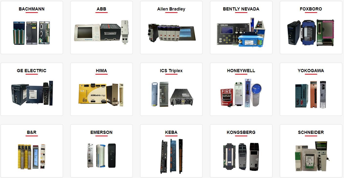 Please make an inquiry for more models
AB 1756-LSP
AB 1756-LSP/B
AB 1756-M02AE
AB 1756-M02AS
AB 1756-M03SE
AB 1756-M08SE
AB 1756-M1
AB 1756-M16S
AB 1756-M16SE
AB 1756-N2
AB 1756-OA16
AB 1756-OA16I
AB 1756-OB16D
AB 1756-OB16E
AB 1756-OB16I
AB 1756-OB16I/A
AB 1756-OB16IEF
AB 1756-OB16IS
AB 1756-OB32
AB 1756-OB32/A
AB 1756-OB8
AB 1756-OF4
AB 1756-OF41794-ADN
AB 1756-OF6CI
AB 1756-OF6VI
AB 1756-OF8
AB 1756-OF8/A
AB 1756-OF81
AB 1756-OG16
AB 1756-OH8I
AB 1756-ON8
AB 1756-OV16E
AB 1756-OV32E
AB 1756-OW16I
AB 1756-OW16I/A
AB 1756-OX8I
AB 1756-PA72
AB 1756-PA72/B
AB 1756-PA72/C
AB 1756-PA75
AB 1756-PA75/A
AB 1756-PA75/B
AB 1756-PA75R
AB 1756-PAR2
AB 1756-PB72
AB 1756-PB75
AB 1756-PB75R
AB 1756-PBR2
AB 1756-PC75
AB 1756-PLS
AB 1756-PSCA2/A
AB 1756-RM
AB 1756-RM2
AB 1756-RM2/A
AB 1756SC-CTR8
AB 1756-SRM/B
AB 1756-TBCH
AB 1756-TBNH
AB 1756-TBS6H
Other best-selling products:


Rockwell Automation announces that as of December 31, 2025, the Kinetix 0.1-0.1m Fiber Optic Ca...
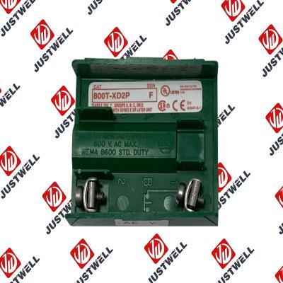
Rockwell Automation announces that as of December 31, 2019, the 30mm Contact Block 1-NC 800T PB...
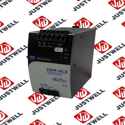
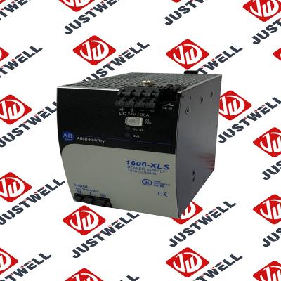
A-B 1606-XLS240E Processor module 24V,10A Single Phase Input Those responsible for the application a...
This document is the original document. All rights to this documentation are reserved by Pilz GmbH &...
Representative Photo Only (actual product may vary based on configuration selections)
Power Supply, 480 W, 24V DC, No Special Function, Performance Family, Global Input Voltage This prod...
Rockwell Automation announces that as of December 31, 2025, the Kinetix Safe Off Header Connect...
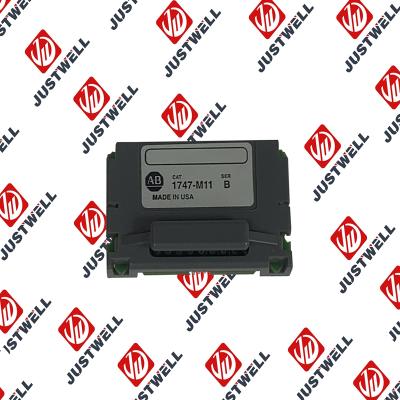
Troubleshooting and Product Information for 1747-M11 Download product information, troubleshooting g...

 IPv6 network supported


