

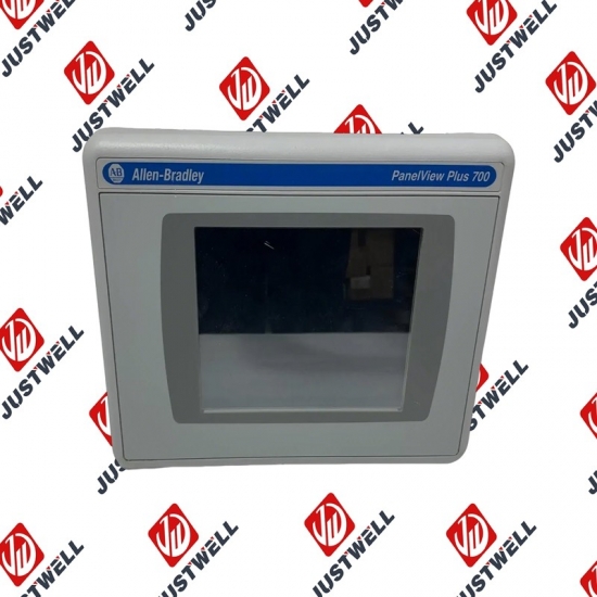
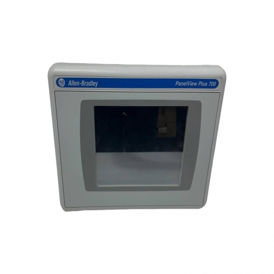

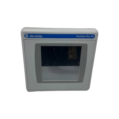
294D-FD4P2Z-G2 A-B analog module
Item NO.:
294D-FD4P2Z-G2Payment:
T/TProduct Origin:
USAColor:
NewLead Time:
IN STOCK294D-FD4P2Z-G2 A-B analog module
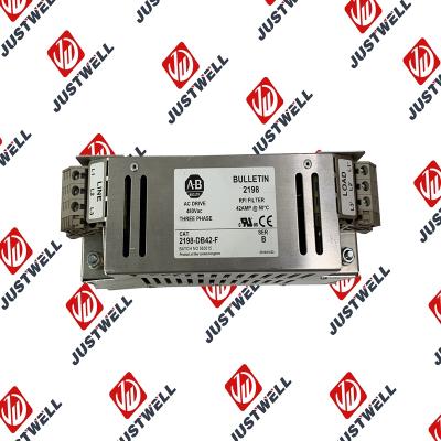
EMC Directive (2014/30/EU) • EN61800-3, adjustable speed electrical power drive systems Part 3: EMC product standard including specific test methods. General Notes • Some drives are equipped with an adhesive label on the top of the drive. If the adhesive label is removed, the drive must be installed in an enclosure with side openings less than 12.5 mm (0.5 in.) and top openings less than 1.0 mm (0.04 in.) to maintain compliance with the LV directive. • Use a motor cable that is as short as possible to avoid electromagnetic emission and capacitive currents. • Do not use line filters in ungrounded systems. • PowerFlex drives can cause radio interference if used in a residential or domestic environment. Follow national and local industrial safety regulations and/or electrical codes, in addition to the essential requirements for CE compliance (see page 7), to prevent radio interference. • Conformity of the drive with CE EMC requirements does not mean that an entire machine or installation complies with CE EMC requirements. Many factors can influence total machine/installation compliance. • PowerFlex drives can generate conducted low-frequency disturbances (harmonic emissions) on the AC supply system. More information regarding harmonic emissions can be found in the PowerFlex 70 EC and 700 VC Reference Manual, publication PFLEX-RM004.
Essential Requirements for CE Compliance These eight conditions must be satisfied for PowerFlex drives to meet the requirements of EN61800-3: • Standard PowerFlex 70 CE compatible drive. • Review important precautions/attention statements throughout this manual before installing the drive. • The drive installation cannot include the encoder interface option (20A-ENC-1, drive catalog number, position 16 must be 0. For example: 20Axxxxxxxxxxxx0). • Ground the drive as described in General Grounding Requirements on page 19. • Output power, control (I/O), and signal wiring must be braided, shielded cable with a coverage of 75% or better, metal conduit or equivalent attenuation. • For B and E frame drives only, ferrite core kit (20A-EMC01) must be installed on the I/O cable, as close to the drive as possible, per Ferrite Core Installation on B Frame and E Frame Drives Only.
The structure and details of the product:
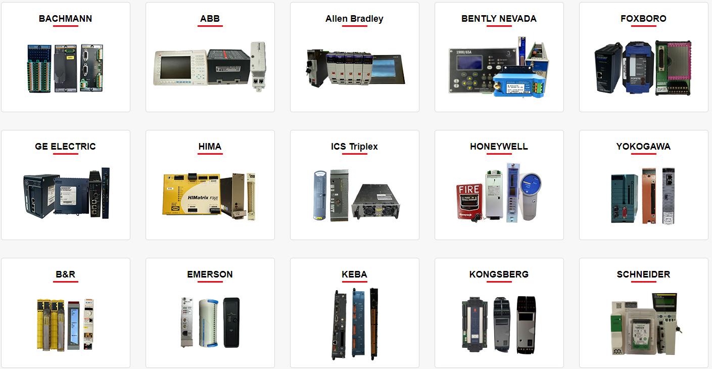 Please make an inquiry for more models
AB 1756-LSP
AB 1756-LSP/B
AB 1756-M02AE
AB 1756-M02AS
AB 1756-M03SE
AB 1756-M08SE
AB 1756-M1
AB 1756-M16S
AB 1756-M16SE
AB 1756-N2
AB 1756-OA16
AB 1756-OA16I
AB 1756-OB16D
AB 1756-OB16E
AB 1756-OB16I
AB 1756-OB16I/A
AB 1756-OB16IEF
AB 1756-OB16IS
AB 1756-OB32
AB 1756-OB32/A
AB 1756-OB8
AB 1756-OF4
AB 1756-OF41794-ADN
AB 1756-OF6CI
AB 1756-OF6VI
AB 1756-OF8
AB 1756-OF8/A
AB 1756-OF81
AB 1756-OG16
AB 1756-OH8I
AB 1756-ON8
AB 1756-OV16E
AB 1756-OV32E
AB 1756-OW16I
AB 1756-OW16I/A
AB 1756-OX8I
AB 1756-PA72
AB 1756-PA72/B
AB 1756-PA72/C
AB 1756-PA75
AB 1756-PA75/A
AB 1756-PA75/B
AB 1756-PA75R
AB 1756-PAR2
AB 1756-PB72
AB 1756-PB75
AB 1756-PB75R
AB 1756-PBR2
AB 1756-PC75
AB 1756-PLS
AB 1756-PSCA2/A
AB 1756-RM
AB 1756-RM2
AB 1756-RM2/A
AB 1756SC-CTR8
AB 1756-SRM/B
AB 1756-TBCH
AB 1756-TBNH
AB 1756-TBS6H
Other best-selling products:


Rockwell Automation announces that as of December 31, 2025, the Kinetix 0.1-0.1m Fiber Optic Ca...
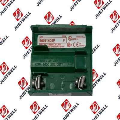
Rockwell Automation announces that as of December 31, 2019, the 30mm Contact Block 1-NC 800T PB...
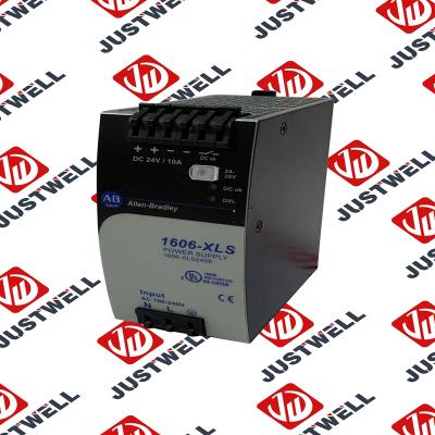
A-B 1606-XLS240E Processor module 24V,10A Single Phase Input Those responsible for the application a...
This document is the original document. All rights to this documentation are reserved by Pilz GmbH &...
Representative Photo Only (actual product may vary based on configuration selections)
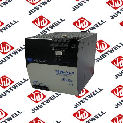
Power Supply, 480 W, 24V DC, No Special Function, Performance Family, Global Input Voltage This prod...
Rockwell Automation announces that as of December 31, 2025, the Kinetix Safe Off Header Connect...
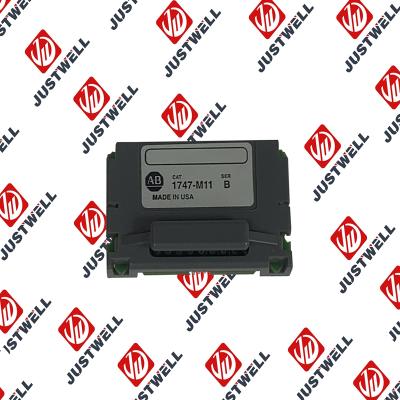
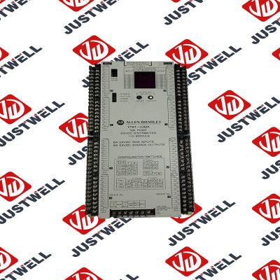
Troubleshooting and Product Information for 1747-M11 Download product information, troubleshooting g...

 IPv6 network supported


