


440L-AM0751650 A-B I / O module
Item NO.:
440L-AM0751650Payment:
T/TProduct Origin:
USAColor:
NewLead Time:
IN STOCK440L-AM0751650 A-B I / O module
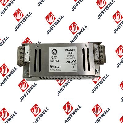
WARNING: EXPLOSION HAZARD • Substitution of components may impair suitability for Class I Division 2. • Do not replace components or disconnect equipment unless power has been switched off. • Do not connect or disconnect components unless power has been switched off. • This product must be installed in an enclosure. All cables connected to the product must remain in the enclosure or be protected by conduit or other means. • All wiring must comply with N.E.C. article 501-4(b). • The interior of the enclosure must be accessible only by the use of a tool. • For applicable equipment (for example, relay modules), exposure to some chemicals may degrade the sealing properties of the materials used in these devices: – Relays, epoxy It is recommended that you periodically inspect these devices for any degradation of properties and replace the module if degradation is found.
Circuits installed on the machine for safety reasons, like overtravel limit switches, stop push buttons, and interlocks, should always be hard-wired directly to the master control relay. These devices must be wired in series so that when any one device opens, the master control relay is de-energized, which removes power to the machine. Never alter these circuits to defeat their function. Serious injury or machine damage could result. Power Distribution There are some points about power distribution that you should know: • The master control relay must be able to inhibit all machine motion by removing power to the machine I/O devices when the relay is de-energized. It is recommended that the controller remain powered even when the master control relay is de-energized. • If you are using a DC power supply, interrupt the load side rather than the AC line power. This avoids the additional delay of power supply turn-off. The DC power supply should be powered directly from the fused secondary of the transformer. Power to the DC input and output circuits should be connected through a set of master control relay contacts.
The structure and details of the product:
 Please make an inquiry for more models
AB 1756-LSP
AB 1756-LSP/B
AB 1756-M02AE
AB 1756-M02AS
AB 1756-M03SE
AB 1756-M08SE
AB 1756-M1
AB 1756-M16S
AB 1756-M16SE
AB 1756-N2
AB 1756-OA16
AB 1756-OA16I
AB 1756-OB16D
AB 1756-OB16E
AB 1756-OB16I
AB 1756-OB16I/A
AB 1756-OB16IEF
AB 1756-OB16IS
AB 1756-OB32
AB 1756-OB32/A
AB 1756-OB8
AB 1756-OF4
AB 1756-OF41794-ADN
AB 1756-OF6CI
AB 1756-OF6VI
AB 1756-OF8
AB 1756-OF8/A
AB 1756-OF81
AB 1756-OG16
AB 1756-OH8I
AB 1756-ON8
AB 1756-OV16E
AB 1756-OV32E
AB 1756-OW16I
AB 1756-OW16I/A
AB 1756-OX8I
AB 1756-PA72
AB 1756-PA72/B
AB 1756-PA72/C
AB 1756-PA75
AB 1756-PA75/A
AB 1756-PA75/B
AB 1756-PA75R
AB 1756-PAR2
AB 1756-PB72
AB 1756-PB75
AB 1756-PB75R
AB 1756-PBR2
AB 1756-PC75
AB 1756-PLS
AB 1756-PSCA2/A
AB 1756-RM
AB 1756-RM2
AB 1756-RM2/A
AB 1756SC-CTR8
AB 1756-SRM/B
AB 1756-TBCH
AB 1756-TBNH
AB 1756-TBS6H
Other best-selling products:


Rockwell Automation announces that as of December 31, 2025, the Kinetix 0.1-0.1m Fiber Optic Ca...
Rockwell Automation announces that as of December 31, 2019, the 30mm Contact Block 1-NC 800T PB...
A-B 1606-XLS240E Processor module 24V,10A Single Phase Input Those responsible for the application a...
This document is the original document. All rights to this documentation are reserved by Pilz GmbH &...
Representative Photo Only (actual product may vary based on configuration selections)
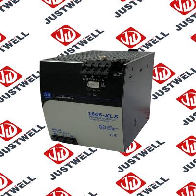
Power Supply, 480 W, 24V DC, No Special Function, Performance Family, Global Input Voltage This prod...
Rockwell Automation announces that as of December 31, 2025, the Kinetix Safe Off Header Connect...
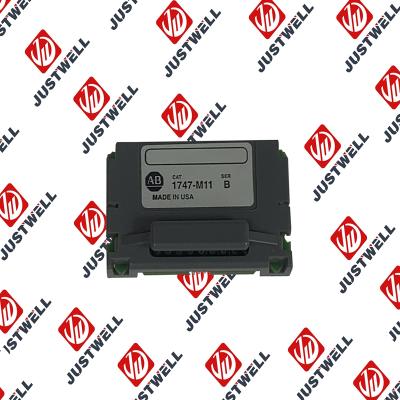
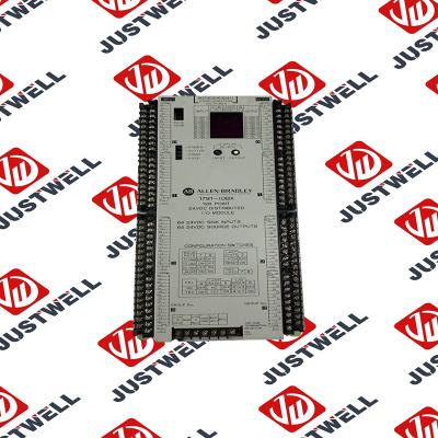
Troubleshooting and Product Information for 1747-M11 Download product information, troubleshooting g...

 IPv6 network supported


