
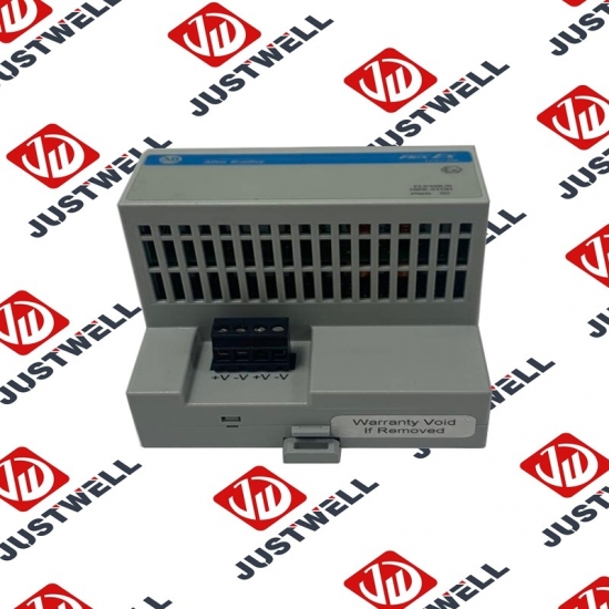
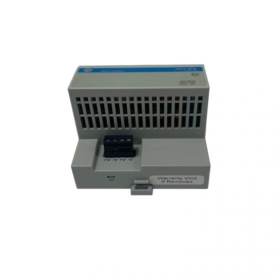


SK-M1-CVR0-E4 A-B Control Unit
Item NO.:
SK-M1-CVR0-E4Payment:
T/TProduct Origin:
USAColor:
NewLead Time:
IN STOCKSK-M1-CVR0-E4 A-B Control Unit
ATTENTION: • Before installing, configuring, operating or maintaining this product, read this document and the documents listed in the Additional Resources section for installing, configuring, or operating equipment. Users should familiarize themselves with installation and wiring instructions in addition to requirements of all applicable codes, laws, and standards. • Installation, adjustments, putting into service, use, assembly, disassembly, and maintenance shall be carried out by suitably trained personnel in accordance with applicable code of practice. • If this equipment is used in a manner not specified by the manufacturer, the protection provided by the equipment may be impaired. • Solid state equipment has operational characteristics differing from those of electromechanical equipment. Safety Guidelines for the Application, Installation and Maintenance of Solid State Controls, publication SGI-1.1, available from your local Rockwell Automation sales office or online at http://www.rockwellautomation.com/literature describes some important differences between solid state equipment and hard-wired electromechanical devices.
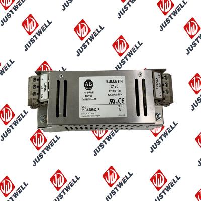
ATTENTION: The drive contains high voltage capacitors which take time to discharge after removal of mains supply. After power has been removed from the drive, wait three minutes to make sure DC bus capacitors are discharged. After three minutes, verify AC voltage L1, L2, L3 (Line to Line and Line to Ground) to ensure mains power has been disconnected. Measure DC voltage across DCand DC+ bus terminals to verify DC Bus has discharged to zero volts. Measure DC voltage from L1, L2, L3, T1, T2, T3 DC – and DC+ terminals to ground and keep the meter on the terminals until the voltage discharges to zero volts. The discharge process may take several minutes to reach zero volts. Darkened display LEDs is not an indication that capacitors have discharged to safe voltage levels. ATTENTION: Only qualified personnel familiar with adjustable frequency AC drives and associated machinery should plan or implement the installation, start-up and subsequent maintenance of the system. Failure to comply may result in personal injury and/or equipment damage.
The structure and details of the product:
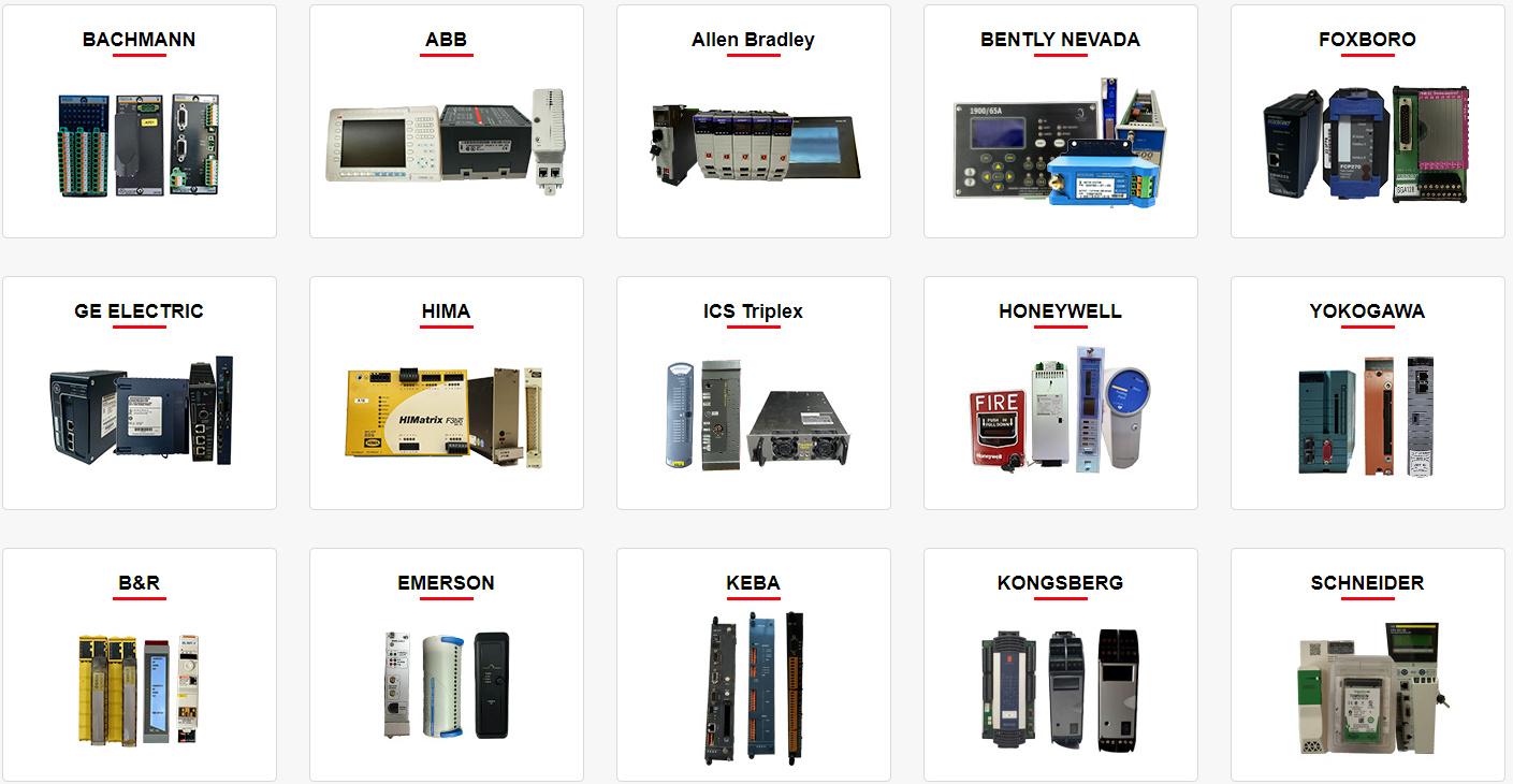 Please make an inquiry for more models
AB 1756-LSP
AB 1756-LSP/B
AB 1756-M02AE
AB 1756-M02AS
AB 1756-M03SE
AB 1756-M08SE
AB 1756-M1
AB 1756-M16S
AB 1756-M16SE
AB 1756-N2
AB 1756-OA16
AB 1756-OA16I
AB 1756-OB16D
AB 1756-OB16E
AB 1756-OB16I
AB 1756-OB16I/A
AB 1756-OB16IEF
AB 1756-OB16IS
AB 1756-OB32
AB 1756-OB32/A
AB 1756-OB8
AB 1756-OF4
AB 1756-OF41794-ADN
AB 1756-OF6CI
AB 1756-OF6VI
AB 1756-OF8
AB 1756-OF8/A
AB 1756-OF81
AB 1756-OG16
AB 1756-OH8I
AB 1756-ON8
AB 1756-OV16E
AB 1756-OV32E
AB 1756-OW16I
AB 1756-OW16I/A
AB 1756-OX8I
AB 1756-PA72
AB 1756-PA72/B
AB 1756-PA72/C
AB 1756-PA75
AB 1756-PA75/A
AB 1756-PA75/B
AB 1756-PA75R
AB 1756-PAR2
AB 1756-PB72
AB 1756-PB75
AB 1756-PB75R
AB 1756-PBR2
AB 1756-PC75
AB 1756-PLS
AB 1756-PSCA2/A
AB 1756-RM
AB 1756-RM2
AB 1756-RM2/A
AB 1756SC-CTR8
AB 1756-SRM/B
AB 1756-TBCH
AB 1756-TBNH
AB 1756-TBS6H
Other best-selling products:


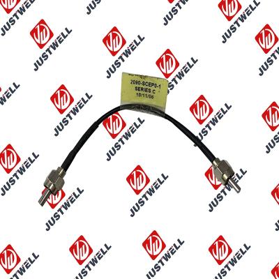
Rockwell Automation announces that as of December 31, 2025, the Kinetix 0.1-0.1m Fiber Optic Ca...
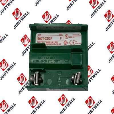
Rockwell Automation announces that as of December 31, 2019, the 30mm Contact Block 1-NC 800T PB...
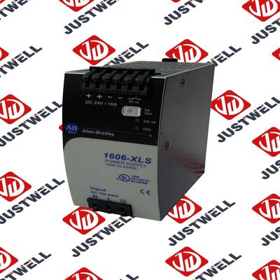
A-B 1606-XLS240E Processor module 24V,10A Single Phase Input Those responsible for the application a...
This document is the original document. All rights to this documentation are reserved by Pilz GmbH &...
Representative Photo Only (actual product may vary based on configuration selections)
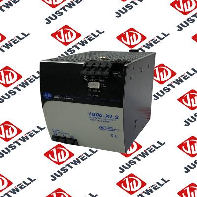
Power Supply, 480 W, 24V DC, No Special Function, Performance Family, Global Input Voltage This prod...
Rockwell Automation announces that as of December 31, 2025, the Kinetix Safe Off Header Connect...
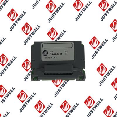
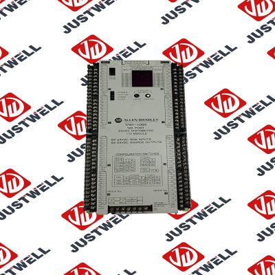
Troubleshooting and Product Information for 1747-M11 Download product information, troubleshooting g...

 IPv6 network supported


