

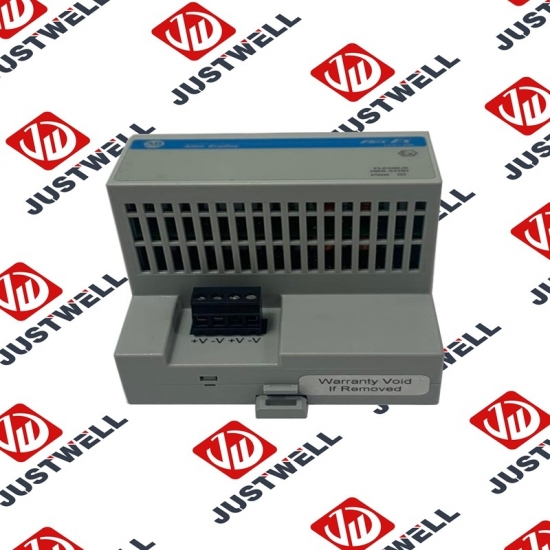
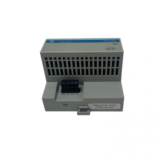


VPL-A0632F-PJ12AS A-B Servo Controller
Item NO.:
VPL-A0632F-PJ12ASPayment:
T/TProduct Origin:
USAColor:
NewLead Time:
IN STOCKVPL-A0632F-PJ12AS A-B Servo Controller
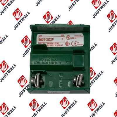
You may want to add a specific circuit to an existing operator/cam assembly. For example, an existing standard operator/cam assembly such as Catalog Number 800T-J2A (standard selector switches use a KB7 cam) may require an XOX circuit. The XOX configuration cannot be accomplished with a single block on this operator (refer to Table 2). Table 5 shows how the XOX circuit can be obtained. Mount a Catalog Number 800T-XA contact block behind either the white or black actuator and wire the N.C. (designated “B” on the cover) and N.O. (designated “A” on the cover) contacts in parallel. Refer to the Typical Wiring Diagrams on Page 15 for series and parallel diagrams. Another example is a Catalog Number 800T-J2KE7 operator requiring an OXO circuit. Refer to the “KE7” cam and index code column in Table 5 on Page 14. The OXO circuit can be obtained from by mounting a Catalog Number 800T-XD2 contact block behind the white actuator and a Catalog Number 800T-XD2 contact block behind the black actuator then wiring the two N.C. contacts in series. Table 6 on Page 15 shows the same functionality offerings for 4 position selector switches.
The target table provides the state of the contacts for each given selector switch position. As indicated in the above examples, operator positions are viewed when looking at the selector switch from the front. Each row represents the contacts of a circuit. The “X” means the contacts are closed and the “O” means the contacts are open. The X and O notations are used in the tables to help with the selection of the correct contact blocks in combined circuits to meet functional requirements. Two separate factors determine if the contact is open or closed in a given position. 1. The “shelf” state of a contact either normally open (A contacts) or normally closed (B contacts). 2. The position of the cam under the White (W) or Black (B) actuator in the given switch position. Note in Table 2 on Page 9 the target tables for the standard selector switch (Cam Code “KB7”), plus Cam Codes “KA1”, and “KA7” are the same whether the contact blocks are mounted behind the white actuator or black actuator. Cam Codes “KC1”, “KC7” and “KD7” have all six contact combinations available.
The structure and details of the product:
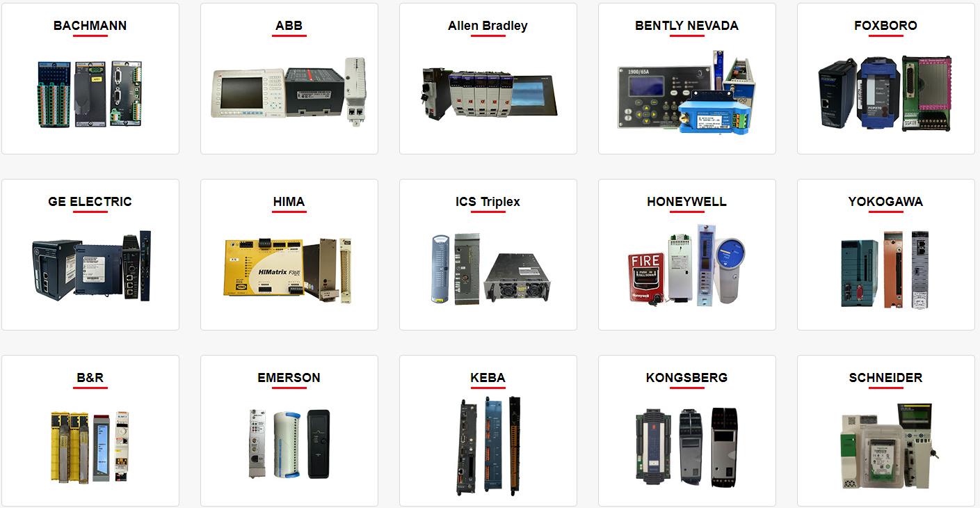 Please make an inquiry for more models
AB 1756-LSP
AB 1756-LSP/B
AB 1756-M02AE
AB 1756-M02AS
AB 1756-M03SE
AB 1756-M08SE
AB 1756-M1
AB 1756-M16S
AB 1756-M16SE
AB 1756-N2
AB 1756-OA16
AB 1756-OA16I
AB 1756-OB16D
AB 1756-OB16E
AB 1756-OB16I
AB 1756-OB16I/A
AB 1756-OB16IEF
AB 1756-OB16IS
AB 1756-OB32
AB 1756-OB32/A
AB 1756-OB8
AB 1756-OF4
AB 1756-OF41794-ADN
AB 1756-OF6CI
AB 1756-OF6VI
AB 1756-OF8
AB 1756-OF8/A
AB 1756-OF81
AB 1756-OG16
AB 1756-OH8I
AB 1756-ON8
AB 1756-OV16E
AB 1756-OV32E
AB 1756-OW16I
AB 1756-OW16I/A
AB 1756-OX8I
AB 1756-PA72
AB 1756-PA72/B
AB 1756-PA72/C
AB 1756-PA75
AB 1756-PA75/A
AB 1756-PA75/B
AB 1756-PA75R
AB 1756-PAR2
AB 1756-PB72
AB 1756-PB75
AB 1756-PB75R
AB 1756-PBR2
AB 1756-PC75
AB 1756-PLS
AB 1756-PSCA2/A
AB 1756-RM
AB 1756-RM2
AB 1756-RM2/A
AB 1756SC-CTR8
AB 1756-SRM/B
AB 1756-TBCH
AB 1756-TBNH
AB 1756-TBS6H
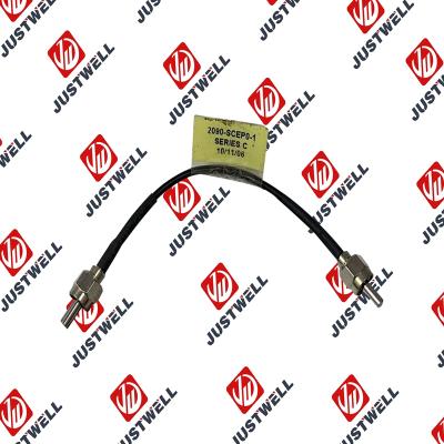
Other best-selling products:


Rockwell Automation announces that as of December 31, 2025, the Kinetix 0.1-0.1m Fiber Optic Ca...
Rockwell Automation announces that as of December 31, 2019, the 30mm Contact Block 1-NC 800T PB...
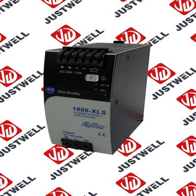
A-B 1606-XLS240E Processor module 24V,10A Single Phase Input Those responsible for the application a...
This document is the original document. All rights to this documentation are reserved by Pilz GmbH &...
Representative Photo Only (actual product may vary based on configuration selections)
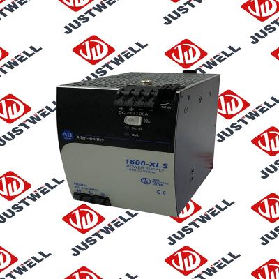
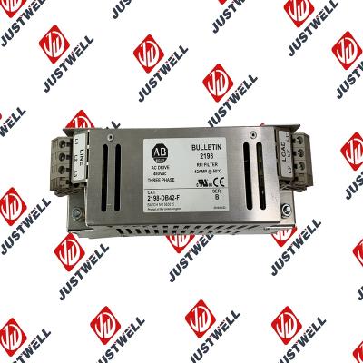
Power Supply, 480 W, 24V DC, No Special Function, Performance Family, Global Input Voltage This prod...
Rockwell Automation announces that as of December 31, 2025, the Kinetix Safe Off Header Connect...
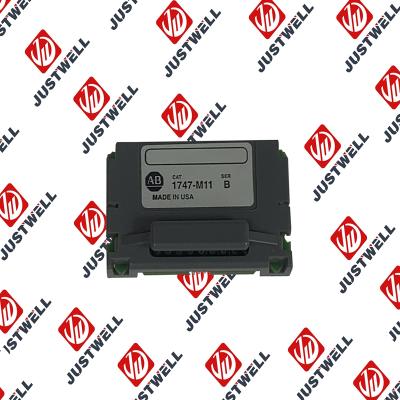
Troubleshooting and Product Information for 1747-M11 Download product information, troubleshooting g...

 IPv6 network supported


